Common Faults&Error Troubleshooting
Faults Troubleshooting (8)
1. Boot does not power up
1) Check if the power cord is connected, if the display is connected correctly;
2) Change the control box.
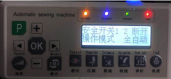
2. Abnormality of display light
F-SENSOR: Lights up when the sensitivity of the first sensor lower then normal (50).
M-SENSOR: Lights up when the sensitivity of the middle sensor lower then normal (50).
B-SENSOR: Lights up when the sensitivity of the behind sensor lower then normal (50).
SAFE: lights up when the safety switch off.
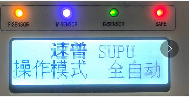
Generally, we turn on the machine, the light is not bright.
If the light of the display bright when turning on the machine, check as follows:
1) Check the line of the sensor is good connected to the plug.
2) Clean the sewing table to make sure the sensor is not covered.
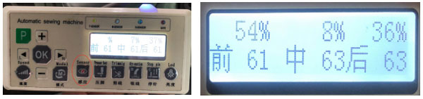
3) Long press the sensor button to enter the sensitivity(there are two rows of values,the first is emission intensity,the second is sensitivity of the sensor. If increase the emission intensity,the sensitivity will be enlarged). Adjust the sensitivities between 60 to 65,we can also use button A (thick material,the value is about 75),button B(middle thick material,the value is about 65),button C (thin material,the value is about 55) to self-calibrating.
4) If the sensitivities can’t be adjusted, change the sensor.
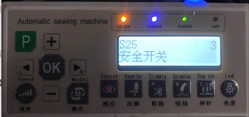
Safety switch bright:
1) If the display shows safety switch off,the light will flash. The safety switch off 1 means the presser foot has not been installed in place,just set it and check the magnet of the presser foot drop or not,or the distance between the magnet and the safety switch is too large. The safety switch off 2 means the the sewing table has not been installed in place, just set it.
2) Long press trimming button to enter S25,check the safety switch is open or not,1 is safety switch of presser foot opening,2 is safety switch of sewing table opneing,3 is two safety switches opening.
3) If it still shows the safety switch off when the sewing table and the presser foot have been installed in place, check the line is good connect to the plug.
4) Change the safety switch.
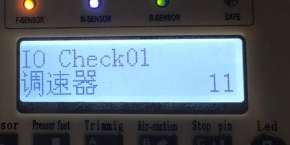
3. Fault of starting up automatic
1) Check the first indicator of the display is bright or not. In the fully automatic mode,the sewing will operat automatic when the first sensor is covered or the sensitivity is abnormal. If the first indicator is bright, clean the sewing table and adjust the sensitivity of the sensor to normal.
2) If the sensor is normal, press the button “P”,and press the trimming button at the same time to enter the governor option,then press the button “OK”. The display will show the voltage of the governor, which normal range should be 150-200. When step backword on the pedal controller, the value should be less than 15. When step forward, the value should be approach 1023. If any value is abnormal, change the pedal controller.
4. Fault of no trimming
No trimming with the hand switch and automatic
1) Check the display if the safety switch off or not. Clean the sewing table, and check the indicator of the sensor bright or not(If the sensitivity of the middle sensor is less than 50, there will be no thread cutting with hand switch ).
2) Power off and check the knife set. Push the electromagnet slide bar to check if the knife set got stuck or not. Check whether the moving knife and the fixed knife have been installed in place. No matter the knife set got stuck or can not cut the line, reinstall the knife set (When cutting line , the moving knife should overlap the fixed knife.
3) If the safety switches, the sensitivities and the knife set are installed in place,check if the plug of the electromagnet slide bar is good connected or not and the contact pins are intact.
4) Change the electromagnet slide bar.
Trimming with the hand witch, but not with automatic
1) Press the trimming button to check whether the function is open.
2) Long press the sensor button and adjust the sensitivities of the sensor to suit different clothes. Generally the value is between 60 to 65. Also we can use button “A” (thick material), button “B”(middle thick material)、button “C”(thin material) to self-calibrate the sensitivities.
3) Check the width of the cloth and the gestures of the operation to make sure the cloth cover the first sensor, the middle sensor and the behind sensor in proper order when sewing normally.
5. Fault of do not lift the Presser foot
The presser foot does not lift automatic, even step backward on the foot control governor.
1)Check the display to make sure if the safety switch off.
2)Check if the plug of the electromagnet slide bar is good connected or not and the contact pins are intact.
3)Change the foot control governor if the voltage abnormal.
4)Change the electromagnet slide bar of the presser foot.
The presser foot does not lift automatic, but lift when step backward on the foot control governor.
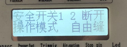
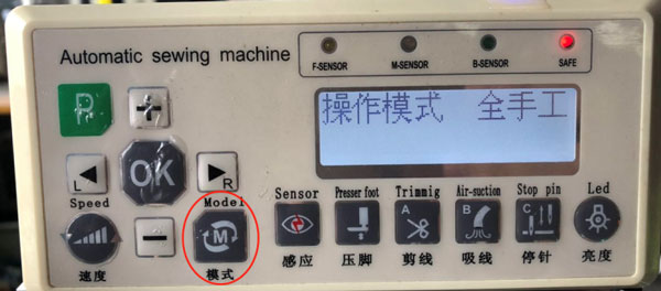
1)Check the operating mode to make sure it is not all manual mode.
2)Clean the sewing table,and adjust the sensitivities of the sensor when the indicator light of sensor bright.
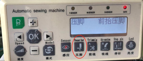
3)Press the “presser foot” button to make sure the function of lifting the presser foot is opened.
6. Fault of Presser foot can’t be maintained
1)Check the electromagnet slide bar of the presser foot lifting has been fully pushed out, and do not resist the limit screw.
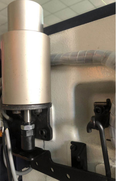
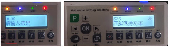
2) Long press the “presser foot ” button, and input the password “2014” to enter S33 (maintained power of the presser foot). Generally, the value is between 20 to 25. The value can not been set too high or it will break the electromagnet.
7. No air suction fault of automatic trimming
1) Press the “air-suction” button to make sure the fuction has been opened.
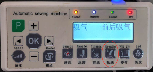
2) Check the sensitivities of the sensors to make sure they are normal
3) Check the solenoid valve plug of the air-suction is good connected

4) Check whether the air pressure is more than 4KG or not
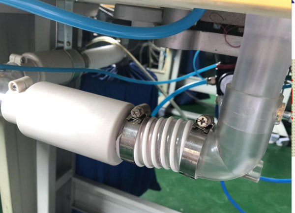
5) Check the Air suction pipe is blocked or not
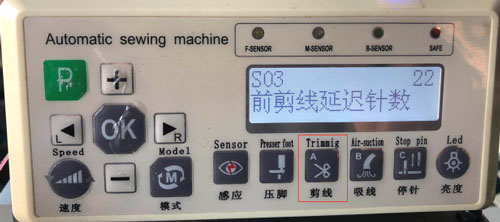
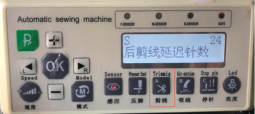
8. Cloth cutting fault of automatic trimming
1)Long press the “Trimming” button to enter S03(Delayed needle count of front trimming).The thread will be shorter when the value was increased. Reduce the value when cutting the cloth.
2)Long press the “Trimming” button to enter S04 (Delayed needle count of back trimming).The thread will be longer when the value was increased. Increase the value when cutting the cloth.
3)Check the meterial, width and the shape of the clothes. Check the worker’s gestures is correctly or not.
Common Error Troubles
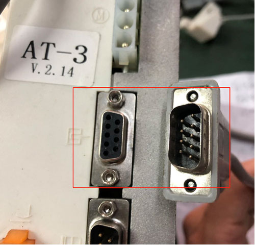
1. Er01 Needle is not found:
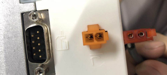
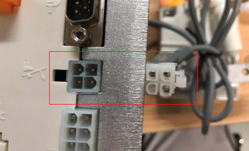
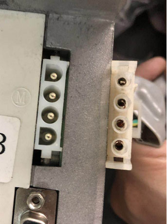
1)Check the nine pin plug is good connected
2)Check the magnet of the hand wheel does not fall off
3)check the distance between the hand wheel and the motor is less then 1.5mm
4)change the control box, if still Er01, change the motor
2. Er02 Boot not detected foot pedal:
1)Check the line of the Foot control governor is good connected to the plug
2)Check the line of the Foot control governor is not bad
3)Change the foot control governor, if still Er02, change the control box
3. Er03 Motor Hall or phase line errors:
1)Check the nine pin plug is good connected
2)Check the Motor rotot is set on the same plane with the coil
3)Change the control box, if still Er03,change the motor
4. Er04 Locked-rotor protection:
1)Turn the handwheel to check the machine is not overweight or got stuck
2)Check the four-core plug is good connected
3)Change the control box, if still Er04, change the motor
5. Er05 Hardware overcurrent protection:
1)Change the control
6. Er07 Serial communication timeout error:
1)Disconnect foot control,if no error,change the foot control
2)Check the line of the display is good connected to the plug
3)Change the display,if still Er07, change the control box
|
Error |
Error code details | Cause of issue |
| Er09 | Bad memory | Damaged or defective motherboard memory |
| Er10 | Light eye control circuit failure | Poor light-eye connection of the display |
|
Er13 |
No signal from the presser foot sensor |
1.The installation distance of the presser foot sensor is too far
2.The presser foot sensor is damaged. 3.The magnet on the presser foot sensor comes off or is reversed. |
| Er14 | Start point sensor cannot find signal | 1.The sensor of the sensor at the turntable is damaged
2.The magnets on the aluminum bar fall off or are installed in reverse |
| Er15 | 9700 error signal | 9700 encoder damaged |
| Er16 | Over voltage fault | Motor drive power supply voltage is too high |
| Er17 | Phase-A current detection failure | |
| Er18 | Phase-B current detection failure | |
| Er19 | Phase-AB current detection failure | |
| Er20 | Under voltage fault | Motor drive power supply voltage is too low |
| Er22 | Foot control problem |
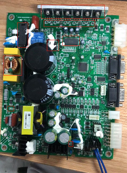
Technical Guide for Electronic Control Repairing of Automatic Trimming
Auto-trimmer repair tips:
1) When we get a PCB circuit boards, we first observe the PCB circuit board to find if there is any component or the copper line on the back burnt out. If not, check the large capacitor at both ends with a multimeter to make sure if the capacitor is conduct or not. And check the fuse is damaged or not, the power tubes got bad or not.
2) If there are no problem, plugged in power. Check the D11 and D9 location of small lights is lighting and notice to the voice of the relay. If the small lights turn on and the relay ring, there will be no problem with the switch power supply. Instead, if there’s any condition not met, it showed the switch power supply got bad.
1.Boot does not power up reason and maintenance instructions
1) When we connect to the power supply, display is not lit.
A. Check the switch is good or not. B. Look at the PCB to make sure there is no obvious burnt out. C. Observe the first LED lights(D11) and second LED(D9). If both lights are not lit, test the fuse, L3 common mode inductors and the power tubes. It will cause a short circuit if a pair of the power tubes got bad. We must replace the 2136 if a group of power tubes got bad. Test the resistor between the power tubes and 2136,and check the 7815.
2) First LED (D11) is lighting, the second LED (D9)is not lighting
A. Check R21(100k). B. Check diode (D6). C. U1(6842). D. Check power supply(Q13). E. Optical coupler (op1). F. D7(MBR20100CT). G. Diode (D4).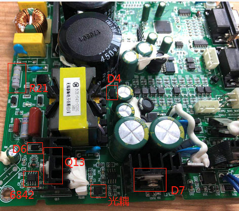
2. Detection
1) F1 Detection of Common-mode inductance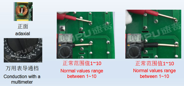
2) Detection of power tubes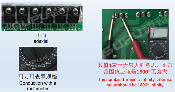
3) Detection of resistance
4) D6 Detection of SMD diodes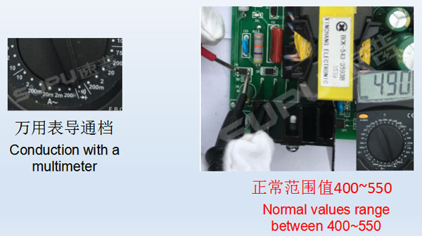
5) U1 Detection of Power supply IC (old PCB)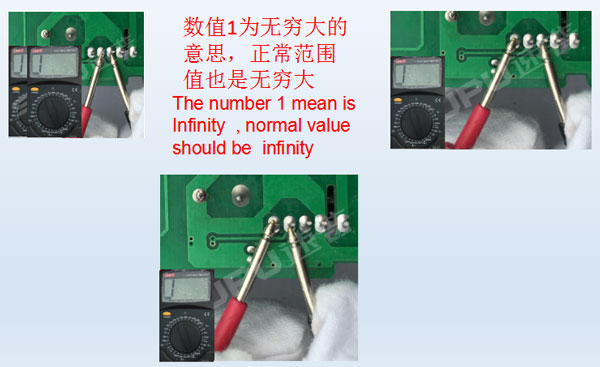
6) OP1 Detection of U10 optical couple
 When we get a PCB that is the new style, check the optical coupler, if the number is lower than 1850,change the 6842(U1).
3. Relay does not ring
1) If the two LED is lighting on the circuit board but the relay does not ring, we should check the D13. If it is normal, change the relay.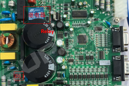
4. U3 output short circuit
1) Check the U3 (SPX1117) with a multimeter in Conduction. If conduct, get down the ZD1 regulator. Then check the U3, if conduct, remove the chip. If still conduction, remove U3. If still conduct, get down U9 (74HC14), if still conduct, take U5 (LM2596), if still conduct, remove the U11 (6002).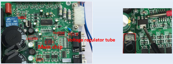
5. Error 01 03
1)First replace a new motor.
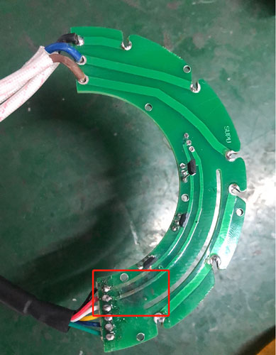
2)Use the naked eye look at nine-pin socket “Figure 1” for damage.
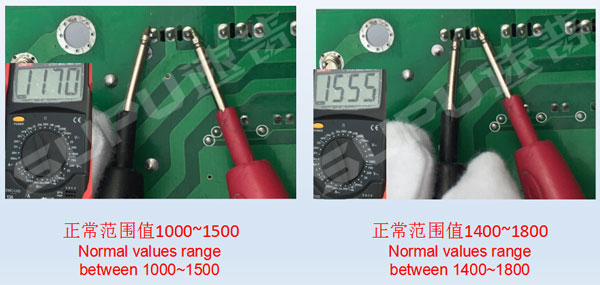
3)Resistance with a multimeter check R82, R78, R75, R73, R71, R69(1K), R83, R79, R76, R74, R72, R70 (4.7K) [Figure 2] resistance is normal in size.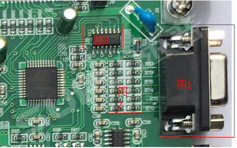
4)If above of all is no problem, directly replace the U9 (74HC14) [Figure 3].
6. Error 02
1) Repleace a new pedal
2) Check the foot pedal socket “Figure 1” for damage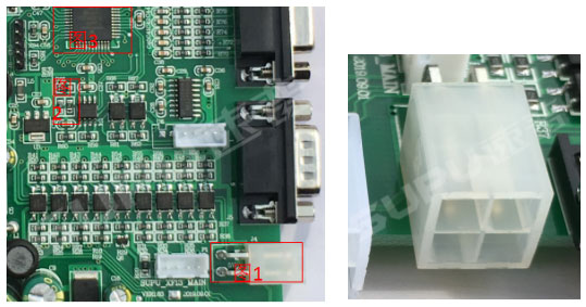
3)Resistance with a multimeter check R65(1k), R4, R40, R47 (1K), R42, R45, R44, R43 (4.7K) [Figure 2] resistance is normal in size
4)If above of all is no problem, directly replace the U7 main chip [Figure 3].
7. Error 04
1)Replace a new motor
2)Check the motor J8 socket for damage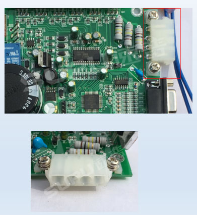
3)Voltage with a multimeter check if U8 (7815)output is 15V, if voltage is 15V, after the class is not a 15V, the diode is bad.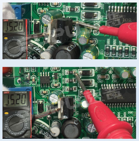
4)D15, D16, D18 diode voltage is not 15V across the diode, forward, after the level of no, the diode is bad.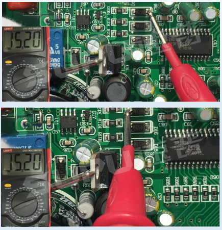
5)If voltage is normal,than replace a new U10.
6)If it’s still bad, then replace U11.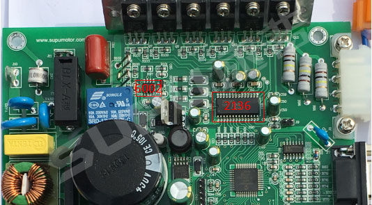
8. Error 05
1) Conduction with a multimeter check the Q7 transistor “Figure 1” 1-2 feet (value around 1700), 1-3 feet (about 1400) 2-3 feet (infinity) numerical fluctuations up and down hundreds is normal, if power bad value at around 100 or below. The multimeter will beep ~ sound. Detection of the power tube. Replace bad power tube down.If you want to replace,then must replace two,like Q7, Q8, Q9, Q10, Q11, Q12. If two power tubes got bad, change the 2136. Check the 7815.Resistance detection of peripheral resistance “Figure 2”.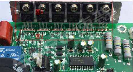
9. Error 07
1) First observe the interface pins of the display to check if there is any obvious damage. Then change a new display.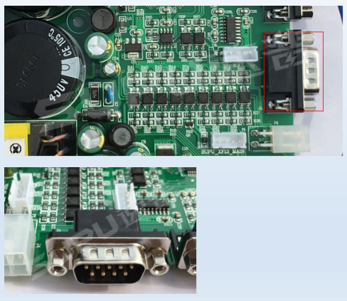
2) First check if ZD1 Zener diode is normal or not. If the ZD1 is good, check the U3 (SPX1117) . If the U3 conduct, take off the mainship U7.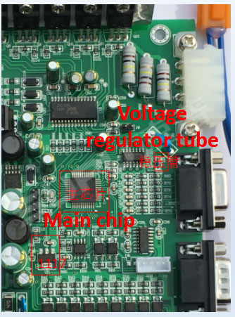
3) Test the voltage of the U2(7805) with a multimeter to make sure the voltage is 5V, if not, the U2(7805) is bad.
4)If all above are good, replace the U6 (MAX232).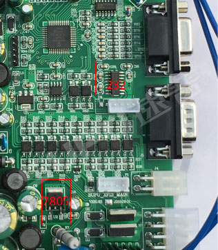
10. Foot peal fault
1)When the presser foot does not work, pull down the presser foot and pick it into the J1 (FOOT 30V). Then turn on the power to test the presser foot work or not. If it works, it means the description J2 presser foot Jack got bad. If not, detect the Q3 (IRF540), A4 optocoupler, and the resistance R44 (510 ω), R53 (4.7K ω), R18 (51 ω), R19 (2.2K ω).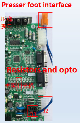
11. Suction failure
1) Observe the J1 (XF 30V) socket damage or not. Then detect the Q2 (IRF540) , optocouplers A2 and R42 (510 ω) R51 (4.7K), the R24 (51 ω), R25 (2.2K).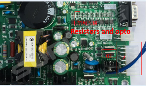
12. Trimmer falut
1) Observe the J1 (cut 30V) socket damage or not. Then detect the Q1 (IRF540) , optocouplers A3 and R43(510 ω), R52 (4.7K), the R27 (51 ω), R26 (2.2K).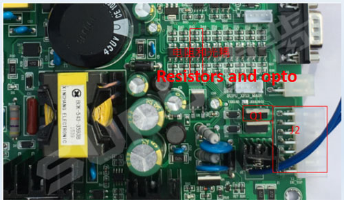
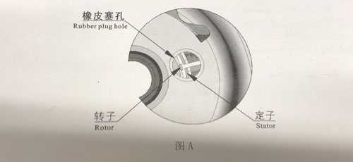
Motor Repairing Guide
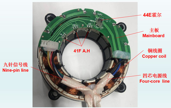
The position of the main parts of the Motor
Er 01 Needle is not found:
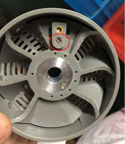
1) Change the stop needle hall which named 44E. (Figure 1)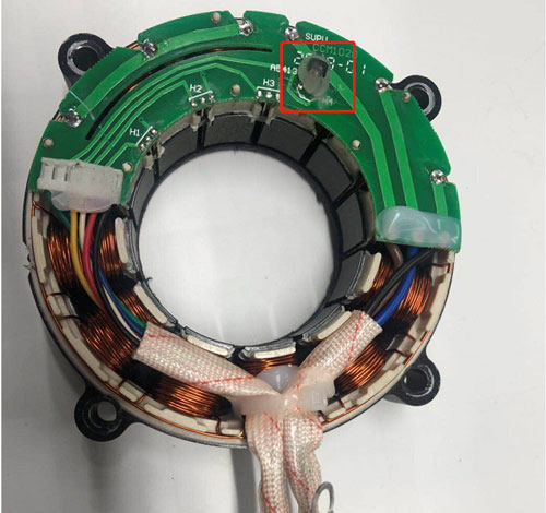
Er 03 Motor Hall or phase line errors:
1) Check the nine-pin signal line is damaged or not.Check the nine-pin signal line with the multimeter. If it is non-conducting, change the nine pin signal line.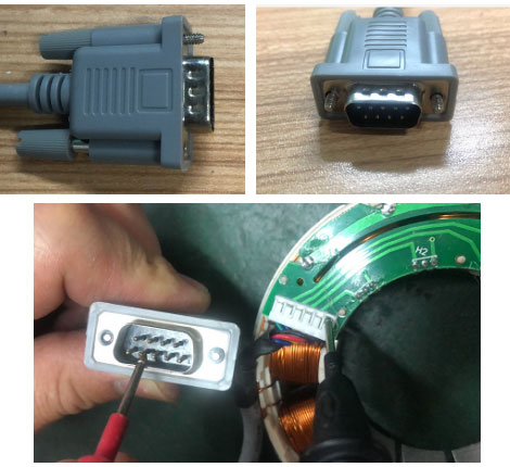
2) Check the driving halls(41F) are damaged or not. Check the driving halls with the multimeter. We should test the positive value and the reverse value. The value of any group got abnormal, change the hall.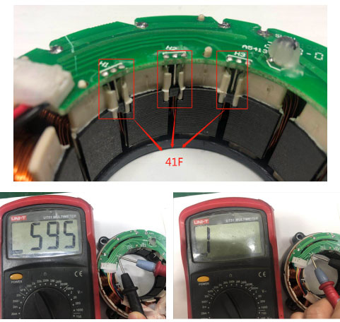
Er 04 Locked-rotor protection:
1) Check the four-core power cord is damaged or not. Check the four-core signal line with the multimeter. If it is non-conducting, change the four-core signal line.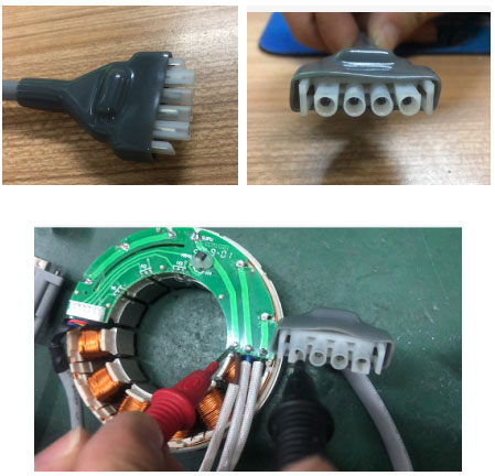
2) Check the copper wire is damaged or not. Open the cover of the motor to check if there is any copper wire broken.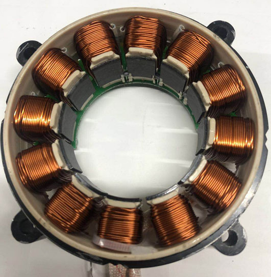
Error Leakage or Coil burning out:
1) When the motor leak, check if the copper coil dropped or contact with the motor housing.
2)Open the cover, if the coil is burnt out, just change it.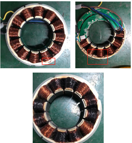
Error Damage of the main-board:
1)Observe the surface of the main-board to check the circuit. We should connect the circuit with the copper wire if it got bad. Change the main-board if it can not be repaired.